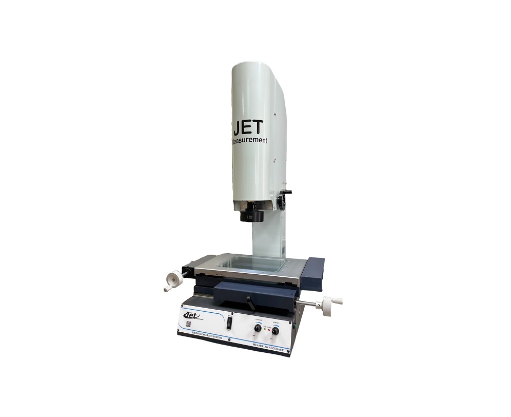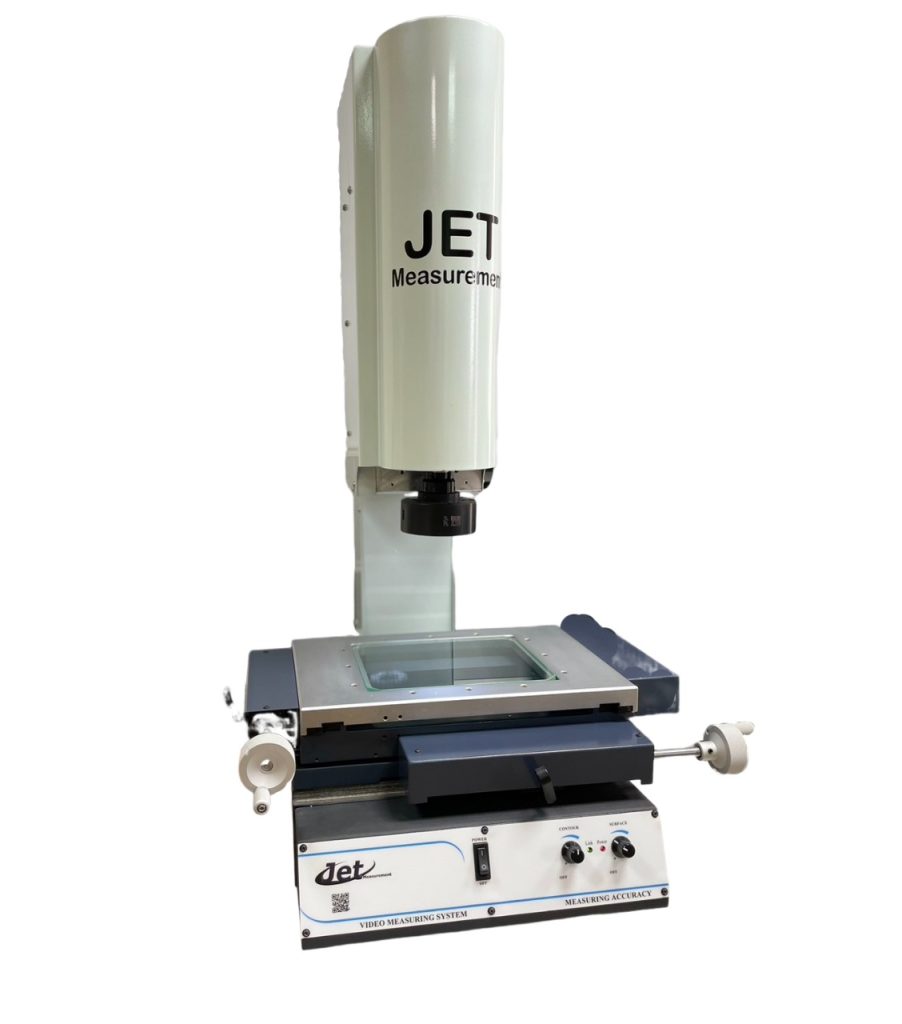
This equipment can be widely used for dimensional measurement, contour analysis, angle detection, hole positioning, geometric tolerance inspection, and surface feature observation of various precision parts. It can quickly and accurately obtain various measurement data of workpieces and assist enterprises in establishing a sound quality management mechanism.
In addition to its dimensional measurement function, it can also serve as a microscopic observation and defect analysis platform to inspect product surface scratches, cracks, burrs, machining marks, plating condition, and assembly quality, effectively improving product quality and testing efficiency. It can also be applied to new product development, process verification, sample comparison, first article inspection, process monitoring, and failure analysis, assisting R&D and quality assurance units in quickly grasping the product quality status.
It is suitable for various industrial manufacturing and precision machining fields, including mold making, precision machinery, metal processing, plastic injection molding, automotive parts, aerospace industry, PCB printed circuit boards, semiconductor packaging, optoelectronic industry, passive components, electronic components, medical devices and academic research institutions, meeting diverse application needs from R&D design to mass production testing.
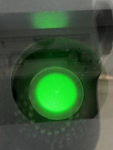
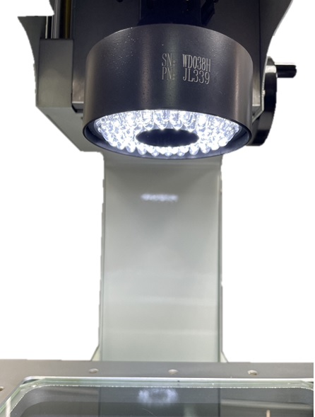
Standard LED lighting system:
High-brightness LED ring light with top light source
Downward-facing telecentric light source green LED
Special applications
This equipment uses high-precision two-dimensional image measurement as its core, establishing measurement benchmarks through points, lines, circles, arcs, rectangles, polygons, and various geometric elements. It can quickly complete the dimensional inspection of workpieces, including length, width, diameter, radius, angle, spacing, position, and contour. For complex contours, irregularly shaped workpieces, and tiny parts, it can also provide stable and highly repeatable measurement results, significantly improving inspection efficiency and accuracy.
In addition to planar dimension measurement, the system can also perform highly correlated measurement operations through auxiliary measurement modules and contact probe devices, realizing the integrated application of two-dimensional and three-dimensional measurement.
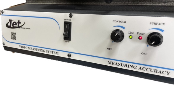
Machine control panel, intuitive operation brightness adjustment, machine and software connection lights
The upper and lower light sources can be turned on and adjusted.
The optimal brightness can be adjusted at will to measure different samples depending on the lighting conditions.
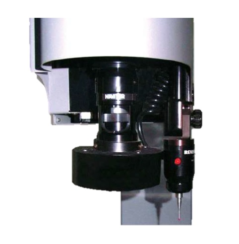
Optional Features | Contact Probe Measurement Module
In addition to standard image measurement functions, the equipment can be equipped with a contact probe measurement module, which accurately obtains dimensional data such as height, depth, steps, and differences by having the probe contact the workpiece surface. It is particularly suitable for the inspection of feature dimensions such as hole depth, groove depth, and dimensions that are not easily measured by optical methods.
Applicable measurement items
✔ Step height measurement
✔ Measurement of hole depth and groove depth
✔ Step height detection
✔ Planar height difference analysis
✔ Measurement of special structural dimensions
✔ Two-dimensional and three-dimensional composite measurement applications
Click here to learn more
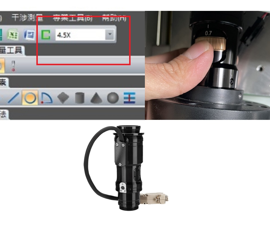
Electronic feedback lens:
Optional feedback variable quilt lens;
When adjusting the magnification, the corresponding magnification of the software will switch accordingly.
Avoid turning the magnification measurement and forgetting to select the corresponding scale on the software
There will be no problem of measurement data errors
Software functions:
Geometric element measurement
Can measure fifteen kinds of geometric elements (point, straight line, plane, circle, arc, ellipse, rectangle, keyway, ring, cylinder, cone, sphere, open curve, closed curve and focal plane)
It can also measure height and preset basic geometric elements.
In addition, upper and lower tolerance limits can be set for the measurement data, and the software can determine whether to display PASS or NG after measurement.
It can measure across spans and perform combined measurements in the drawing area at the bottom right of the software. It can also be saved as a CAD file.
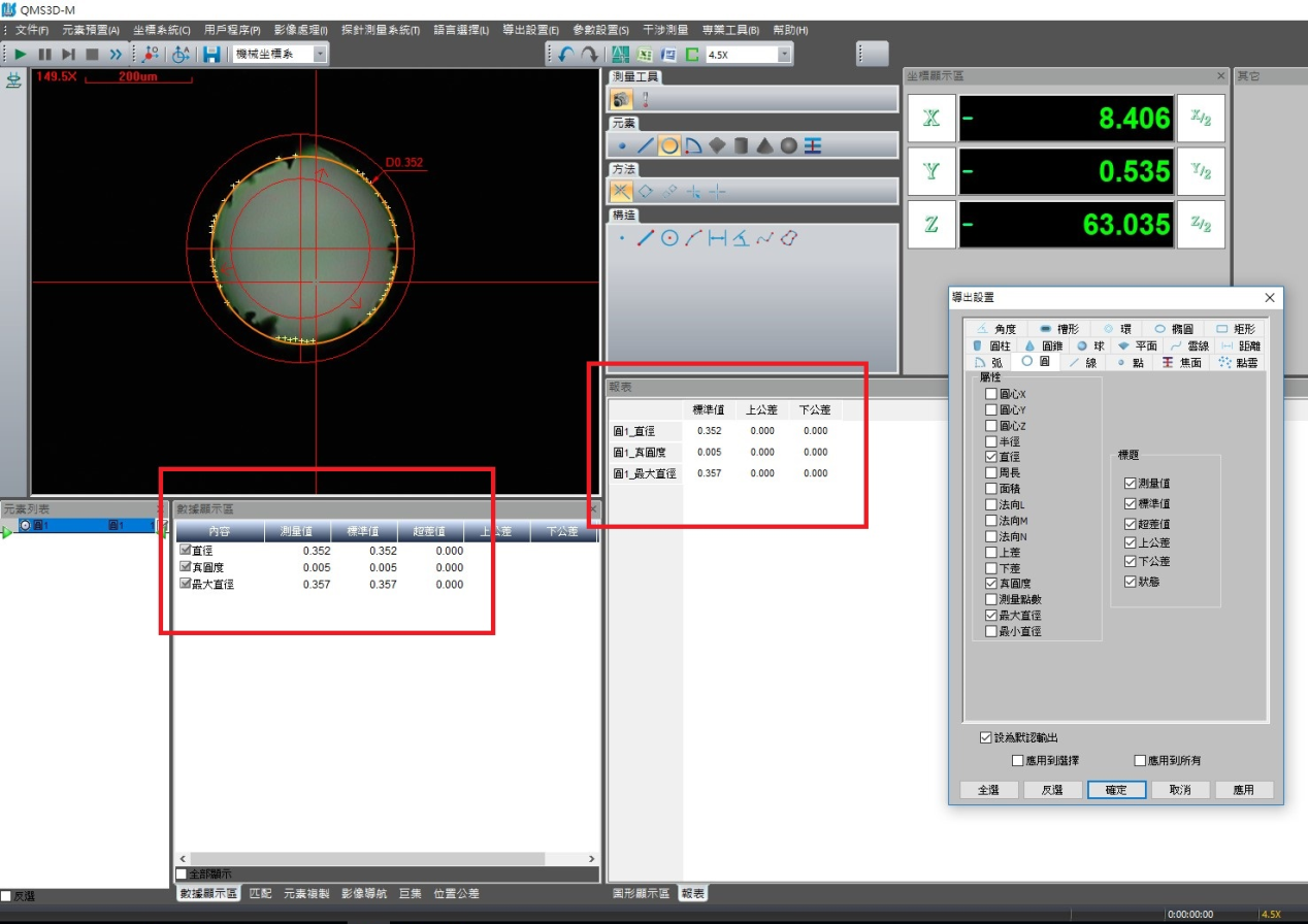
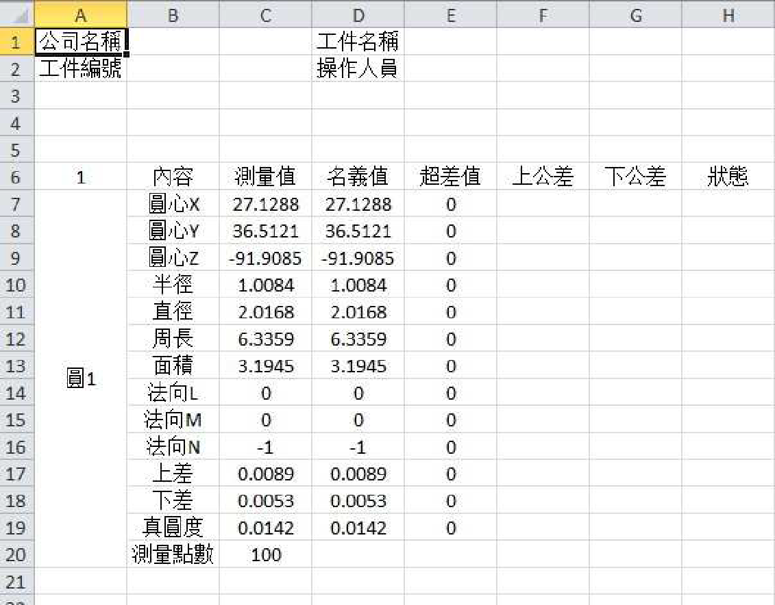
Multiple report export formats
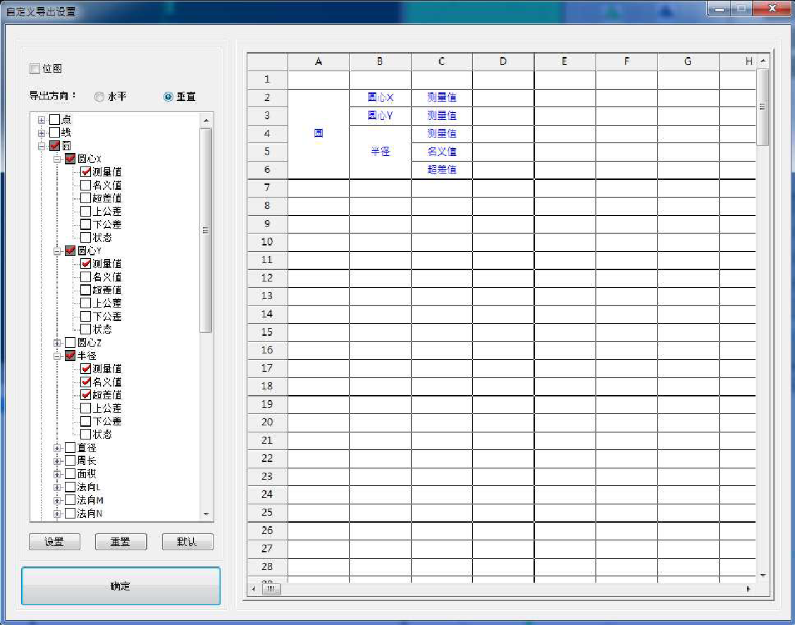
You can set the exported content of elements, the export direction, and whether to export bitmaps.
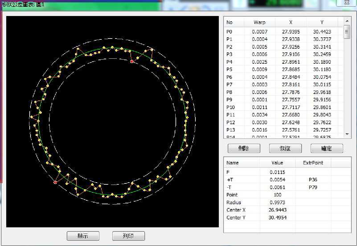
Geometric tolerance measurement
Shape Tolerance Chart:
Measure the shape tolerance charts of straight lines, circles, planes, cylinders, and balls. You can delete measurement point errors as needed.
If the difference is large, you can print the shape tolerance chart of the element and view the shape tolerance attributes.